LDG Z-817 Review and there is a BIG SECRET Reveal

This is a purpose built tuner for the Yaesu FT-817/817ND and 818 QRP radio

It can handle 20 watts and uses latching relays to conserve its built in (4 AA) battery power

It can remember 2000 memory points to quicken tuning withing 2 seconds

Coverage is 1.8 to 54 Mhz and it is continuous so no issues using it on 60m or even the maritime bands

The range is excellent covering from 6 to 600 ohms. The tuner on the Icom 7300 is 16 to 150 ohms so you can load up a couple of shopping carts or my “Crutches” antenna

The tuner interfaces with the FT-81x with a foot long CAT cable making integration fast and simple.

Just push the button and GO

The BIG SECRET is that this tuner can be used with other QRP radios by just transmitting a carrier and pressing the TUNE button. Of course you dont need the CAT cable

Remember 20 Watts max power so it will work with your Clansman, Yaesu, Icom 705 or even the Transworld Fly Away radio

BTW I will be using this with the Icom 705 with a pretty simple 5x5x2 inch box

Unboxing the Icom 705 – English Translation

ICOM’s “IC-705” is a portable device that covers the HF to 430MHz band in all modes. As previously reported , Wakayama Icom Arita Factory made its first shipment to the whole country on the afternoon of June 19th (Friday), and it seems that it arrived at the wireless shop in the early morning of Saturday, June 20th in the early areas . Since the hamlife.jp staff also received it at the local shop, I will post the usual “opening report”.


IC-705 received at a local wireless shop the first morning on June 20. The size of the box is as small as 270 W × 225 H × 175 Dmm


 The main body size of IC-705 (excluding protrusions) is 200W x 83.5H x 82Dmm, and the main body weight (including attached battery) is about 1.1kg. Perhaps because of that, the box of IC-705 handed over at the wireless shop was surprisingly small (measured approximately 270 W x 225 H x 175 Dmm) and light (measured approximately 2.14 kg).


 There was a thin tray when the lid on the top was opened, and there was a warranty card, an instruction manual, a postcard for user registration, a errata for the instruction manual, a license application entry guide, and a JARL enrollment guide.

When I opened the lid, the top tray had a warranty card, an instruction manual, and a JARL membership guide.

I lined up what was in the tray. Warranty, instruction manual, postcard for user registration, errata of instruction manual, license application entry guide, JARL enrollment guide etc.


 Removing the tray and the protective cardboard below it, the IC-705 body, battery pack (BP-272), speaker microphone (HM-243), DC power cable, spare fuse (4A x 2), CW key plug , The microphone mounting plate, etc. were subdivided into plastic bags and contained.


The IC-705 body was visible when the tray and protective cardboard were removed.

IC-705 body, battery pack (BP-272), speaker microphone (HM-243), DC power cable, spare fuse (4A), CW key plug, microphone mounting plate, etc.

The size of IC-705 looks like this. Height and width are close to 500mL plastic bottles. It weighs about 1.1 kg including the attached battery pack, so it’s like two plastic bottles (500 mL + 600 mL).


 The attached battery pack (BP-272) had a capacity of 1880mAh, and had a capacity of about 1/3 when shipped. The battery itself is made in Japan, but it says “ASSEMBLED IN CHINA”. The speaker microphone that fits comfortably in your hand is made in China. The angle of the clip with the Icom logo on the back can be changed. The PTT has an unexpectedly strong spring impression.


Battery pack (BP-272)

Rear of speaker microphone (HM-243)


 A sticker with a serial number is attached to the battery pack mounting part on the back of the main unit. The construction design certification number (technical suitability number) is 002-200001, and Icom has recertified the certification for 1.8MHz band SSB. Please note that the power will not turn on unless you firmly attach the battery pack’s claws so that it clicks.


There is a sticker on the back of the main unit where the battery pack is attached, with a serial number and a technique number.

Sticker part with serial number etc.

Battery pack must be installed firmly


 When the battery pack is attached and the POWER button on the front panel is pressed, the power turns on and the 14.100MHz display appears after the opening screen. GPS positioning started immediately. By the way, the firmware installed is “Version 1.08”. Since it is the same version that Icom released on its website on June 19, there is no need to upgrade the firmware at this time.


Attach the battery pack and turn on the power for the first time! GPS positioning started immediately


 Click here for the LC-192 multi bag we received together. It was surprisingly light and compact.


I also received the optional multi-bag, LC-192. There was a pouch at the handle and there was a camera screw for mounting the main body.


 By the way, the IC-705 reservation privilege, the rice cracker, has not been opened yet. Some people also worried that “Is the expiration date for tiled rice crackers on the IC-705 postponed?”, but it was confirmed that the stated expiration date was September 15, 2020, which is a sufficient number of days.


IC-705 Receiving a tiled rice cracker (senbei), which is a special benefit of the booker. The expiration date was also sufficient


 From around 20 noon on Twitter, tweets such as “I bought the IC-705 at a wireless shop” and “I turned on the power at once” are being written one after another. Some people disassemble the interior as early as possible, or report the difference in transmission output due to the power supply voltage, and some people do field tests by connecting an antenna. Such information may also be useful to those considering purchasing. Why not try searching with the keyword “IC-705” on Twitter.


Icom Rice Cracker

Rice Cracker or Leather Looking Things in a Box

Homemade Rice Cracker Recipe

Ingredients

  • 2.5 cups cooked sushi rice
  • 1 teaspoon sweet smoked paprika
  • Salt and Pepper

Instructions

  1. Preheat your oven to 180 degrees Celsius
  2. Place the cooked leftover sushi rice in a bowl.
  3. Add the spice and seasoning (if needed) the amount of salt you will require will depend if your sushi rice was seasoned when cooked
  4. Mix so that the spice is evenly distributed
  5. Line a baking tray with baking paper
  6. Wet your hands and a tablespoon, Use the wet spoon to and your wet hands to form golf ball sized rice balls
  7. Place the balls on the baking tray
  8. Top with another layer of baking paper, then squish the balls evenly. You could use your hands for this, a rolling pin, or I used a chopping board and pressed down so that all the balls were squashed at the same time
  9. Bake at 180 degrees for approximately 20-24 minutes.. remove from the oven before the edges get too golden
  10. Allow to cool, they should be quite crunchy when coo

FB Girls tried IC-705 and LC-192! – English Translation

<Episode 30> FB Girls tried IC-705 and LC-192!

Monthly FB news editorial department

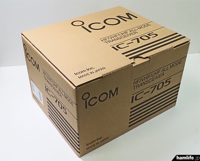
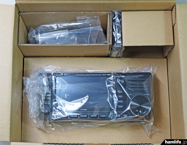
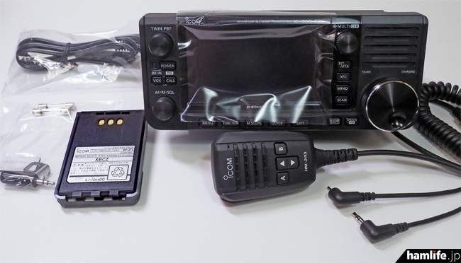
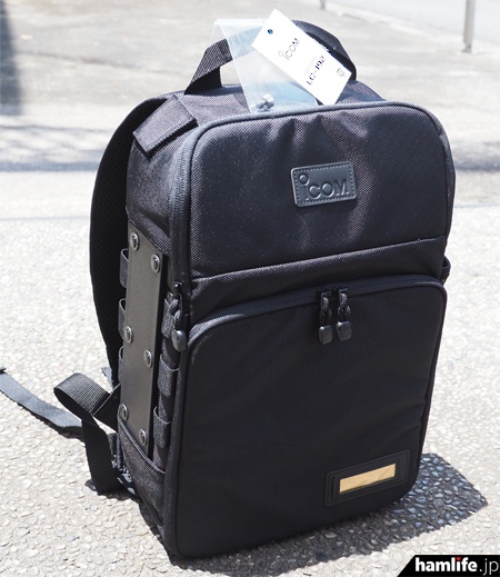
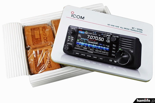
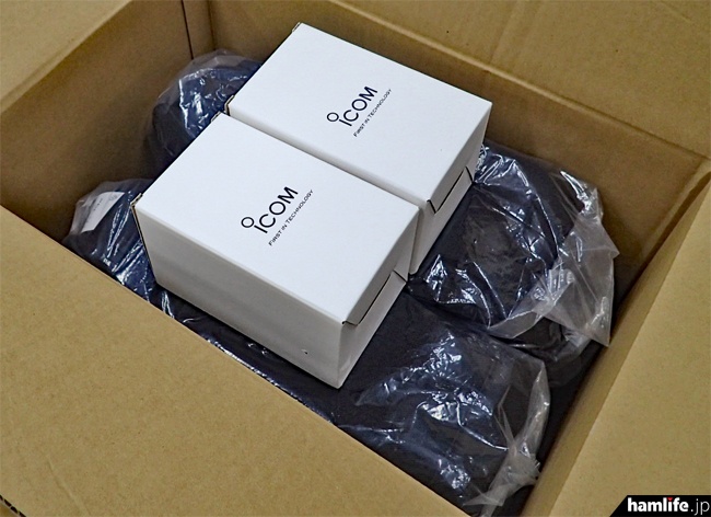
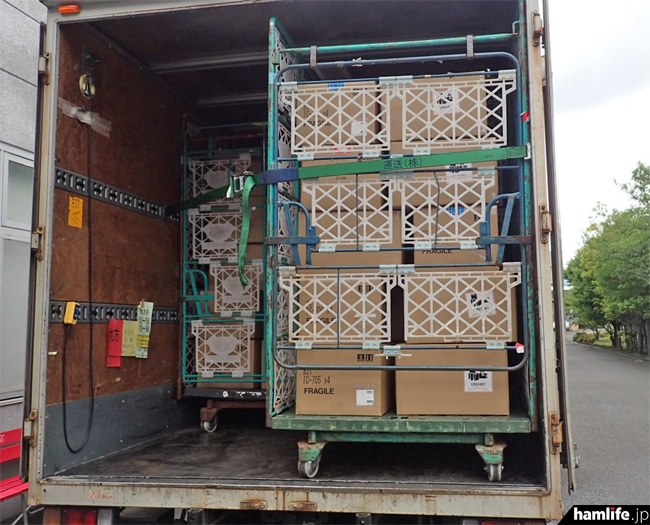
The long-awaited IC-705 and dedicated rucksack LC-192 have arrived at FBGRC (FB Girls Radio Club), courtesy of Icom Co., Ltd. We apologize for the large number of readers who have booked but have not yet received it, but I will report it a little earlier.

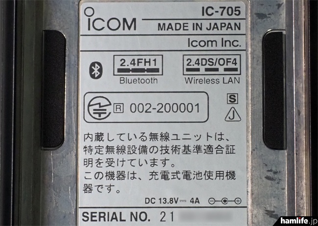
First of all, in order to add IC-705 in advance, I applied for a license change for JL3ZGL, a corporate group bureau, but the license was granted by the Kinki Bureau of Communications as of June 1. At this point, 3MA/4MA did not yet include SSB and AM, so the 1.9MHz band was described as “3MA J3E A3E 1910kHz”. If J3E and A3E will be included in 3MA/4MA in the future, it will be simply “3MA 1910kHz”.

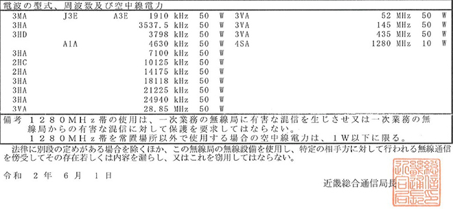
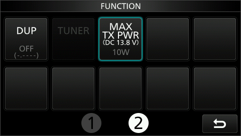
However, when actually operating SSB and AM in the 1.9 MHz band (1.8 MHz), it is necessary to deploy an efficient antenna (for example, a full-size dipole antenna) with 10 W output, and the IC-705 QSO It may not be easy to do, but readers who think it’s my own should definitely try it.

Go to Yamato Katsuragiyama!

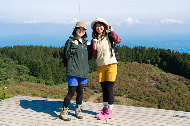
Masaco and Erie set up the just-received IC-705 on the LC-192, a special rucksack, and aimed for Yamato Katsuragiyama (959m) on the prefectural border between Osaka and Nara.


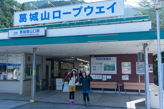
Guts pose at the ropeway platform at Katsuragi Tozanguchi Station!

Since Mr. Masaco visited not only during the interview in March this year but also twice before that, he knows how to buy the ticket and how to board.


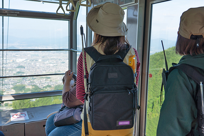
The weather was fine on this day and the view from the gondola was great.

On the other hand, Erie will be visiting for the first time, and Masako will guide her. “That is Yamato Sanzan, and from the left, Mt. Kogu, Mt. Uneyama and Mt. Earnari!”

Arriving at Katsuragi Yamagami Station after about 6 minutes boarding, we will depart for the summit.
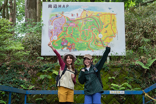

Let’s go!

There is a continuous climbing path from Katsuragiyamajo Station, which is the landing point of the ropeway, to the summit, and you need some physical strength. There is no problem for Mr. Masaco who is a sports girl, but it is a tough road for Ellie who is a cultural girl.


The ID-51 is attached to the shoulder straps of the LC-192,
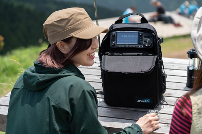
but two people who purposely ragchu with the IC-705 put in the backpack

Even if you are a little far away, you can continue talking normally because of the wireless communication. No problem at all. In fact, there is a theory that he wanted to do QSO with the IC-705 he brought, so he purposely climbed a distance. (Mystery)


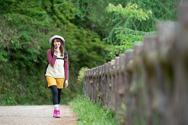
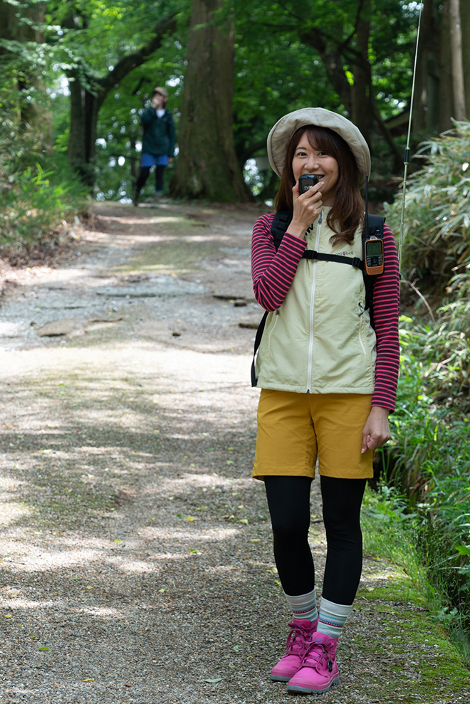
Masaco at my own pace

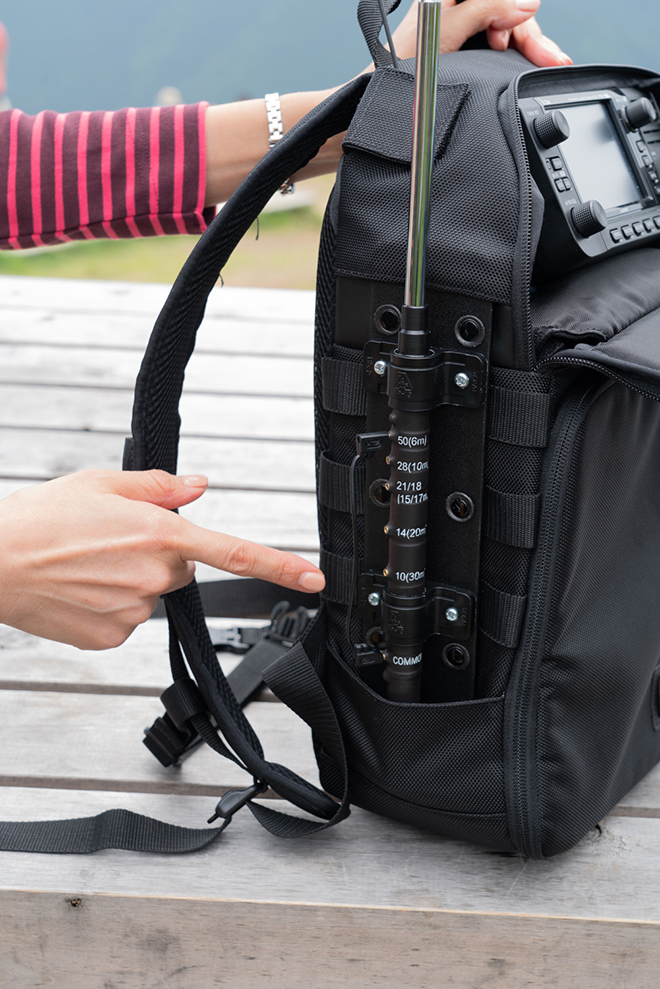
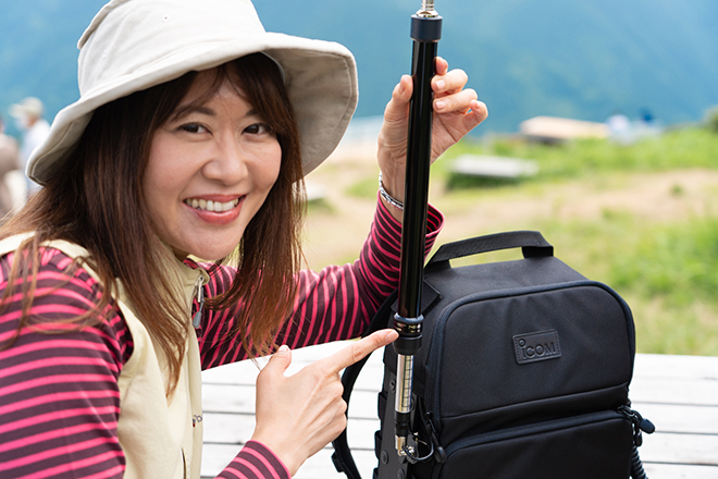
Even if you can’t see the following one, it’s okay because there is a radio. You can operate IC-705 while walking by using LC-192. The V/UHF band whip antenna can be taken out from the upper antenna hole by relaying it with the BNC-L-shaped connector. (Details will be described later)


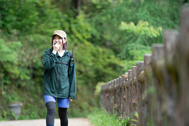
Ellie continues after a delay.

By the way, Erie is an individual call operation because IC-705 has been added to the personal station license.


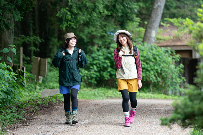
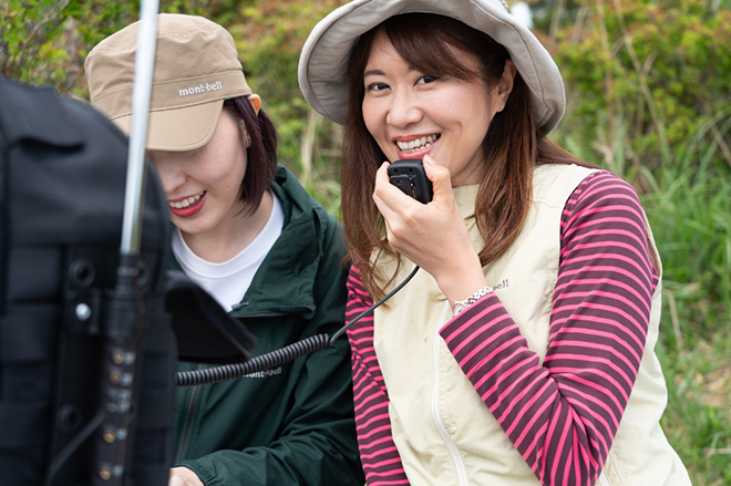
When walking side by side, let go of the microphones and AF ragchu.


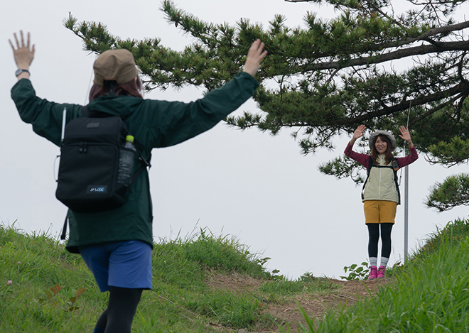
Mr. Masaco who arrived at the top of the mountain welcomes Erie.

After climbing the mountain road of about 1 km, the two arrived at the summit.


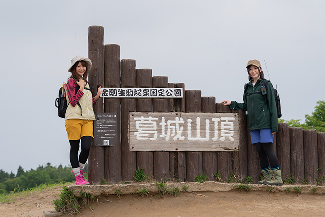
This place seems to be photographed on the summit camera every 10 minutes.


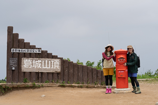
There is also a post box (operating only from spring to autumn) installed at the top of the mountain

After taking a commemorative photo at the top of the mountain, we moved to a wooden bench a little further down and prepared for full-scale operation.

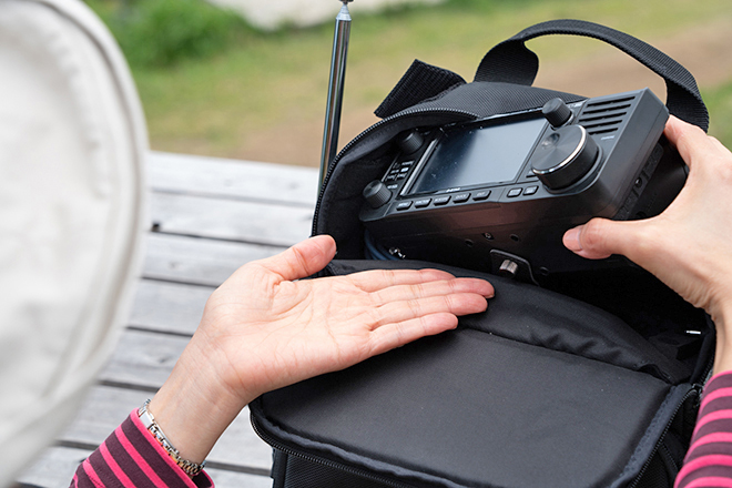
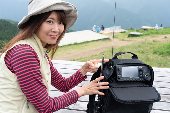
Prior to the operation, Mr. Masaco explained the LC-192.

Fixing IC-705 body to LC-192

A belt for fixing the IC-705 is attached to the upper space of the LC-192. Use the screws provided with the LC-192 to secure this belt to the IC-705 body. As a result, the LC-192 and IC-705 are connected, so the main body will not fall down even if tilted.


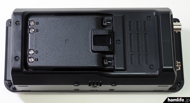
The state of the camera screw on the bottom

Installing the VU whip antenna

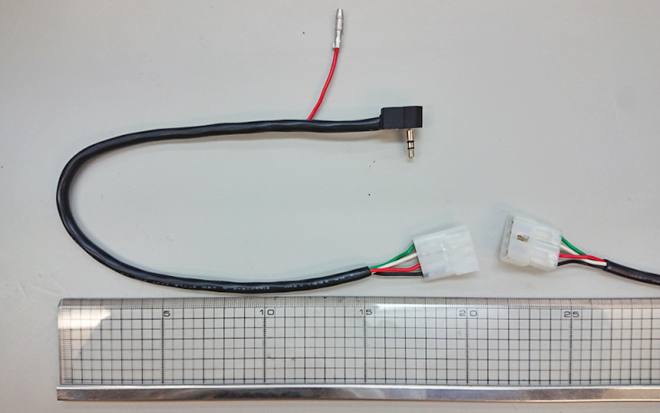
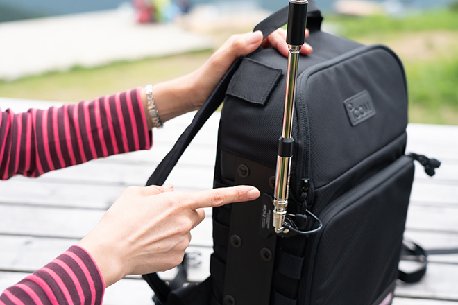
First, attach a commercially available BNC-L type relay connector to the antenna connector on the main unit.

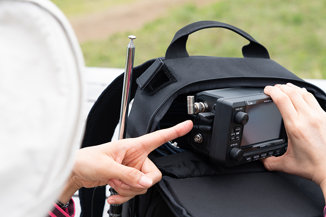
Insert the connector side of the antenna into the LC-192 from the antenna hole on the top of the LC-192 and connect it to the BNC-L type relay connector.

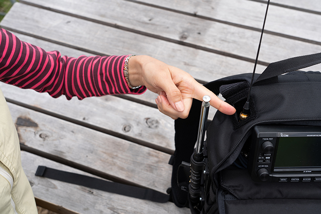
This is complete. If it is an antenna for a handy device, you can immediately operate the V/UHF band in this state. When I watched the 430MHz band, the band was so crowded that I could not imagine it in the lower world.

HF rod antenna installation example

There are various possible methods for mounting the HF antenna, but this time we will introduce two mounting examples using commercially available antennas.

1-1 Comet HFJ-350M

Using the plastic plate on the LC-192 side, fix the coil part of the HFJ-350M with a commercially available nylon saddle. HFJ-350M’s movable part is only the upper rod part, so this is OK. The trick is to attach it so that the jumper wire insertion port is on the front side.


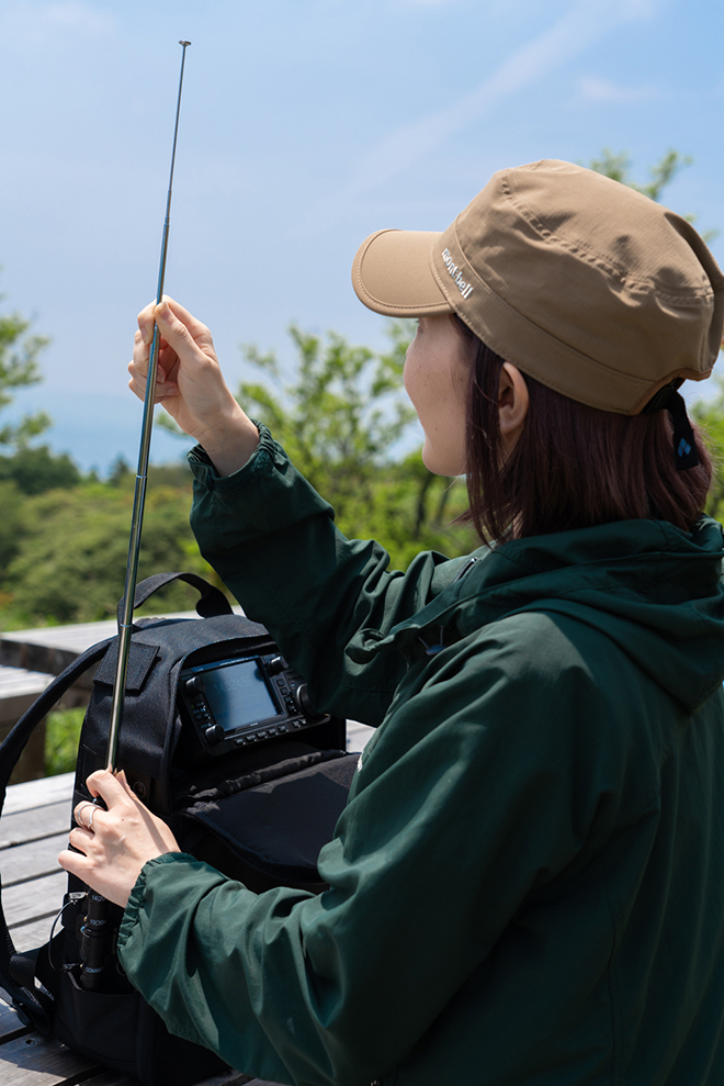
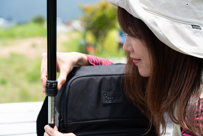
Ellie adjusting the antenna at the rod

1-2 diamond RHM8B

Since the base of RHM8B is movable, it cannot be fixed to the plastic plate on the LC-192 side with a nylon saddle. For this reason, the company’s clip base MCRⅡ is used to fix the plastic plate.
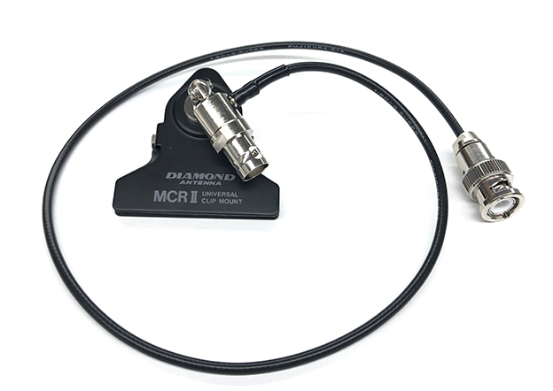

MCRⅡ


Adjusting the movable coil part and adjusting the antenna

It is difficult to walk with both HFJ-350M and RHM8B because a counterpoise must be connected to the antenna base to install and operate these antennas.

A VU whip antenna can also be attached by using a commercially available MCRⅡ.


When I attached RH770 of the company to MCRⅡ of diamond

Let’s operate!

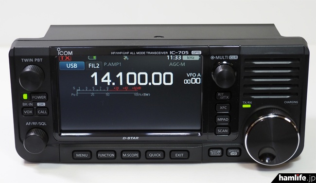
We decided to operate in the 7MHz band, which is popular with domestic QSOs. On this day, not only the weather but also the conditions were good, and stations all over the country were impressed. The spectrum scope of IC-705 is convenient for searching for an empty frequency in such a case.

By using the real-time spectrum scope of the IC-705, you can see the band status in the field operation as well as the fixed machine operation at home, and renew the conventional field operation.


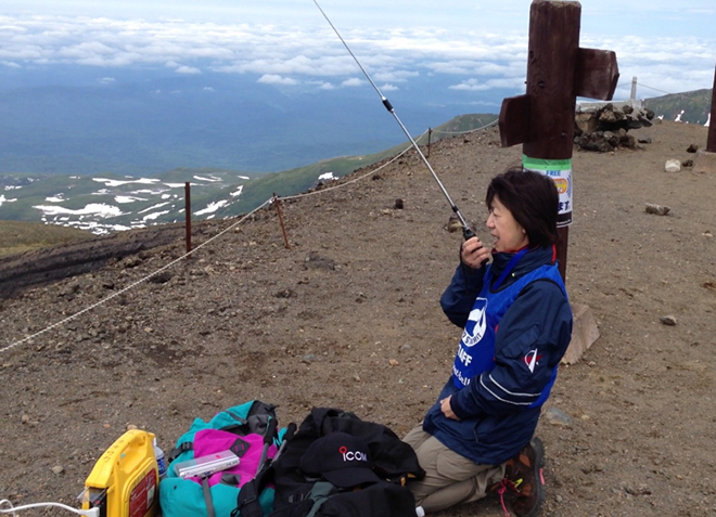
CQ CQ CQ This is JL3ZGL/3 JL3ZGL/3 Gosho City, Nara Prefecture, please

Masaco, who used the spectrum scope to find free frequencies, immediately put out CQ. But there is no response. After that, I gave CQ many times, but there was no response. With 5W output SSB, it looks pretty tough. Even so, I was tenacious and continued to issue CQ, and there were calls from stations in 6 areas. It was a moving moment. I sent 59, but the report I received was 57. Well, it’s like this.

Even after finishing QSO with all the stations in 6 areas and issuing QRZ, it is a scene. Although the condition is good, the situation is quite different from the 50W operation with the dipole antenna that is always used in the mobile operation of JL3ZGL.

When I issued CQ, there were calls from stations in 3 areas. I was able to communicate with 13 stations in a short period of operation, partly because I got a response in such a condition and I was uploaded to J cluster on the way. I was thrilled to be able to QSO with 5W stations in 1 area on the way.


2 Ama’s Ellie tried CQ with 14MHz CW, but unfortunately no response.


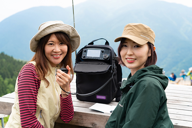
Two people who survived 5W operation with YL power.

LC-192 Masaco version

Finally, Mr. Masaco showed me the inside of LC-192.

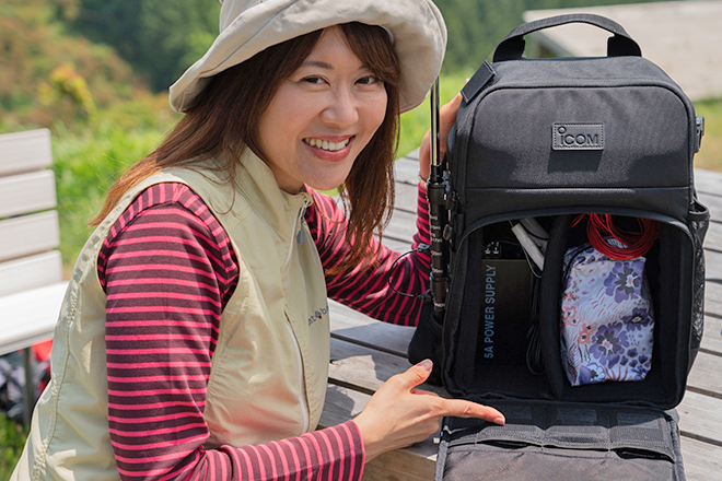
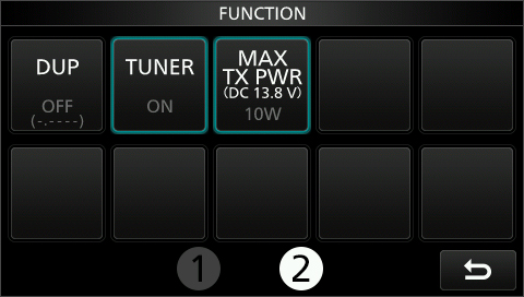
On the left side of the partition board is the Diamond power supply DSP500. This is said to be used when charging the battery of IC-705 or when operating at 10W from the hotel when AC power can be secured, such as when returning to the hotel.

On the right side of the partition board, there was a 10m long 0.5SQ vinyl wire for radial operation and a decorative pouch for HF operation.

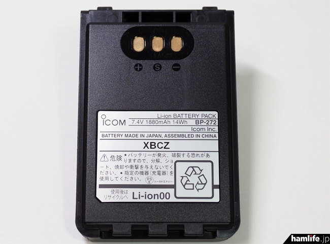
Three spare battery packs in the mesh pocket. It seems that you are preparing for long-term operation.

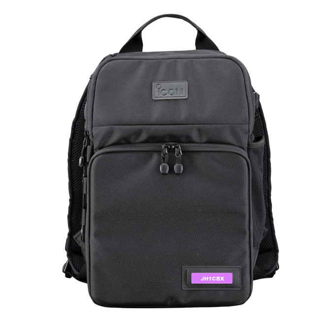
Also, since LC-192 has a name plate holder, Masaco made a name plate with a call sign using the template downloaded from the Icom website. There are 12 types of templates with different designs on the homepage, and anyone can easily make a color copy.

Nameplate creation template:
https://www.icom.co.jp/lineup/options/LC-192/#nameplate


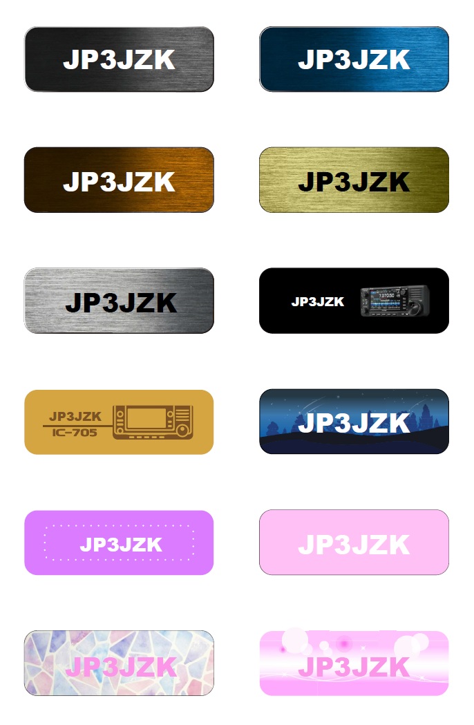
12 types of templates prepared on the Icom website


“If you put in a callsign, you’ll look like an amateur radio operator, right?” by Masaco


Commemorative photo with two people in front of Shimoyama

Although it does not fly as usual in SSB operation with 5W, the radio wave is still working properly, and this time I found that I could enjoy playing as if I could communicate with Kyushu. If I have the opportunity, I would like to carry out the second operation.

Fin.

(Note) The content of wireless communication that appears in the article is different from the actual one.

Icom starts factory shipment of new product “IC-705” on June 19th (Friday) – English Translation

Icom starts factory shipment of new product “IC-705” on June 19th (Friday)

It was in time for the E-spo season! Factory shipment of ICOM’s HF-430MHz band all-mode portable device “IC-705” began on June 19, 2020 (Friday). It is expected to arrive at some wireless shops as early as Saturday 20th. hamlife.jp dispatched an interview staff to the Wakayama Icom Arita Plant, which is the production base of IC-705, and succeeded in taking a photo when loading the truck. With the start of shipment of the IC-705, the latest firmware (Version 1.08), programming software (CS-705), and USB driver of the same model were released respectively, and RS-MS3A, an application for setting terminal mode/access point mode, A new version of the Android-only app RS-MS1A compatible with IC-705 has also been released.


Click here for the article posted on June 20, the fastest open report ↓
<Wait for half a year!! Finally came to my house> ICOM “IC-705” open report


IC-705 (at Wakayama Icom Arita Plant) in a state of waiting for packaging after manufacturing and aging.

Icom’s IC-705, which covers the HF to 430 MHz band in all modes including DV (D-STAR’s digital voice), was released for the first time in 38 years at the company’s Ham Fair 2019 venue as a portable machine for the first time in 38 years. became. After that, development and manufacturing proceeded, and Wakayama Icom Arita Plant (Aritagawa Town, Arita District, Wakayama Prefecture) Has started shipping products to retailers nationwide.

After 1:00 pm on that day, IC-705 cardboards on pallets were loaded one after another onto the trucks of the shipping company that was laid next to the factory. One cardboard box contained four IC-705 packages and four boxes of “original tile crackers” that would be gifted to all the reservations made up to this point.

Cardboard box containing IC-705 placed on a pallet

One IC cardboard contains four IC-705s and four “roof rice crackers” that will be presented to the subscriber (wrapping paper in the red box).

The “IC-705 original canned rice cracker (rice cracker)” will be presented to everyone who reserves the IC-705 so far. 18 pieces (3 sheets x 6 bags) of 7 cm square tile rice crackers with the IC-705 model name and the front panel branded in an original metal can printed with a beautiful color photograph of IC-705. There is. It was said to have been manufactured by a tile cracker manufacturer in the middle of June (Photo provided by Icom

Next, the optional multi-bag “LC-192” and the cardboard box containing the original LED lantern of the purchaser privilege (first 1,000 people) were loaded in the same way.


The optional multi-bag “LC-192” and the original LED lantern presented to the first 1,000 people were also loaded.

Completed loading on the truck of the shipping company. If it’s a relatively close wireless shop, it’s expected to arrive tomorrow 20th.


It is expected that these will arrive at some wireless shops tomorrow at the earliest and will be handed over to the subscribers in sequence.

The production of the IC-705 was never “100% smooth” due to unexpected production interruptions due to the influence of the new coronavirus, but somehow “the time for the E-spo season was met” Officials seem to be at ease.

In addition, on June 19, Icom released the latest firmware (Version 1.08) of the same model, the CS-705 programming software, and the USB driver with the shipment of the IC-705. Also, a new version of RS-MS3A for using terminal mode and access point mode and RS-MS1A for android only application corresponding to IC-705 has been released.

●Related links:
・IC-705 Firmware Version1.08 (Icom)
・Programming software CS-705 (Icom)
・USB driver for IC-705 (Icom)
・Terminal mode/access point mode setting software RS-MS3A
・Android only App RS-MS1A
/IC-705 Product Information (Icom)
/IC-705 Instruction Manual PDF (Icom)
/IC-705 Usage Manual PDF (Icom)

Using antenna tuner AH-4 with IC-705 JK3AZL Naoka Takaoka – English Translation

Technical corner

Using antenna tuner AH-4 with IC-705

JK3AZL Naoka Takaoka

Shipment of IC-705 to retailers has started. The antenna tuner for the IC-705 is “to be released”, but “I want to use the wire antenna with the IC-705 soon”, so I tried to verify whether the AH-4 can be used with the IC-705.

IC-705 TUNER Jack and plug pin assignment

The IC-705 has a “TUNER jack” on the right side, and is said to be “connectable to an IC-705 dedicated antenna tuner that will be released at a later date.”


IC-705 TUNER jack position.

The TUNER plug is a 3-pole stereo plug with [KEY], [START], and [GND] assigned from the tip.


Pin assignment of IC-705 TUNER plug.

To connect AH-4 to IC-705

IC-705 does not have AH-4 connector like IC-7610 or IC-7300, but connect each control line from AH-4 side and GND to TUNER jack, and separately add 13.8V to AH-4. Once supplied, the IC-705 will also be able to use the AH-4…


Connection diagram of AH-4 and IC-7300. The AH-4 is powered by 13.8V from the radio itself.


Connection diagram of AH-4 and IC-705. Connect AH-4 and IC-705 to the same external power supply, and ground properly from the GND terminal.

To connect AH-4 to IC-705, connect each control line (KEY and START) and GND line from AH-4 side to the tip and ring of Φ3.5 stereo plug so that 13.8V can be supplied separately. To process. You can get a Φ3.5 stereo plug at a parts shop, but if you just want to verify the operation, a screw-type conversion connector is convenient.


The screw-type conversion connector that can be wired directly to the 3-pin terminal is convenient for wiring confirmation.

To connect the IC-705 and AH-4, prepare either of the following cables.
(1) AH-4 control cable that is specially processed for IC-705 connection using Φ3.5mm plug.
(2) A conversion cable to be attached to the AH-4 control cable connector using the AH-4 connector (female side) parts.

In the case of (1), the control cable attached to the AH-4 will be processed, so I would like to avoid this, and use one side of the separately purchased 4-core shielded cable as the J2 connector of the AH-4 and the other side. Processed so that it can be connected to IC-705. (Red part of the above connection diagram)


The purchased 4-core shielded cable. It can be purchased in units of 1m, and there is a discount if it exceeds 10m.

In the case of (2), a cable of several tens of centimeters is sufficient, so if there is no problem with shortening the control cable that comes with the AH-4 standard, cut the required length from the AH-4 main unit side before using. Would be fine. The shell and pin of the AH-4 side connector (female side) of the conversion cable can be requested for purchase (cash on delivery) from the Icom Support Center mail form.


Parts for AH-4 connectors can be ordered from the Icom Support Center mail form.


A conversion cable that I made by ordering the AH-4 connector (female side) parts.

Connection and operation check

Since the IC-705 has not arrived at hand, I borrowed the display machine of the ham shop to check the operation. When checking the IC-705 function screen before connecting the AH-4, it is natural that [TUNER] cannot be selected.


IC-705 function screen before AH-4 connection.

Next, connect both AH-4 and IC-705 to the same stabilized power supply with the power off, and turn on the power in the order of AH-4 → IC-705. When I checked the function screen of IC-705, the text [TUNER] was displayed in white this time, and when I touched it for a long time (about 1 second), it changed from OFF to ON.


IC-705 function screen after connecting AH-4.

When tuning is started with the external antenna tuner, the [TUNE] display flashes red in the upper left of the IC-705 screen, and when tuning is completed, the [TUNE] display changes to lit.


TUNE display on the upper left of the IC-705 screen. When tuning is done, it lights up as shown in the figure.

Precautions when using the AH-4 and expectations for a dedicated antenna tuner

By connecting AH-4 to IC-705, it was confirmed that it works theoretically. I was able to tune without any problems, but it seems that there are some bands whose detection of tuning completion is more severe than other radios. The tuning power of the AH-4 is 10W, and the instruction manual for the AH-4 also states “If you are using a 10W machine, set the transmission output to high power (10W).” In conclusion, I feel that it is possible to operate with IC-705 connected to AH-4, but it is also necessary to divide it from provisional operation.

The IC-705 is compact and can be operated with a battery. In order to maximize the enjoyment, I wanted a dedicated antenna tuner as soon as possible!


At the summit of Asahidake, Hokkaido. I used RH-770 to communicate with ID-51 in the 144MHz/430MHz band.
With the IC-705 and a dedicated antenna tuner, the fun of wireless is likely to spread.

Enjoy the RICE CRACKERS AND LANTERN

Let’s Go T-Hunting

Let’s Go T-Hunting

by Joe Moell, K0OV

Motor City Radio Club – W8MRM

The Longest ARRL Affiliated Club in Michigan”

Here’s an introduction to RDF contesting in southern California, updated from a paper originally submitted for Proceedings of the West Coast VHF/UHF Conference. Put this article in your ham club newsletter to encourage members to try T-hunting. (See the copyright notice at the end.)

VHF/UHF enthusiasts often install yagis and quads at their home stations. Many take them out on camping trips and use them on public service events. But did you know that some enjoy flying the freeways and beating the back roads with one hand on the steering wheel and the other on a rotating antenna mast?

Perhaps you have seen these hams on weekends, intently driving and turning their beams. What are they doing? They are competing in hidden transmitter hunts.

If you’ve never experienced one of these mobile radio direction finding (RDF) contests, you have missed some of the greatest excitement a ham can have. While there are several names for it such as “fox-hunting” and “bunny chasing,” in southern California this sport is almost always referred to as “T-hunting.”

Transmitter hunting seems to be one of the best kept secrets in ham radio, even though dozens of hams here consider themselves to be regular hunters. They range in age from the teens to the eighties. Besides keeping the coordinated two-meter hunt frequency (146.565 MHz FM) hopping, hunters love to hash over their exploits by the hour on their favorite repeaters.

The idea is simple: One or two hams take a transmitter, antenna, and some sort of distinctive audio source to an carefully selected spot, then make continuous or intermittent transmissions. Usually they remain stationary, though mobile “bunnies” are popular with some groups. Sometimes there are more than one “T” to be found. Surplus ammunition cans are often used as hidden transmitter enclosures. The hunters, as individuals or in teams, do their best to home in on the hidden station(s) with their mobile and portable RDF gear.

Fun, But Beneficial

T-hunters think their events are more fun than any other ham contest. You get to meet and socialize with your competitors both before and after the event. Usually, you’ll find out your score and how well you placed before you go home. You may encounter your competitors along the way, with opportunities to try to “psych them out” or misdirect them. (Hence the southern California maxim: “Never trust anything said by a T-hunter or hider.”)

“Techies” like the thrill of finding the hidden T with gear they made themselves. They relentlessly work to improve their setups. Mystery lovers and dyed-in-the-wool contesters love the challenge, because very hunt is a fresh start to a new adventure. Your past performances are forgotten. It’s just your team and your equipment against today’s hider and the other hunters.

At some point, every ham will find knowledge of RDF techniques useful, because it simplifies such chores as finding a neighborhood source of power line interference or TV cable leakage. T-hunters here frequently are called upon to track down sources of “spurs,” intermodulation and noise that can plague amateur (and sometimes commercial) repeaters.

RDF plays an important part in Amateur Radio self-policing. In many areas of the country, including southern California, there are standing agreements between Local Interference Committees and district FCC offices, permitting volunteer ham RDFers to gather evidence leading to prosecution in serious cases of malicious interference.

You have up to a dozen competitive hunt opportunities to choose from every month in Los Angeles, Orange, Riverside and Santa Barbara Counties. They are all different in some way, such as time or mileage scoring, day or night start, single or multiple transmitters, intermittent or continuous signal, wide or narrow boundaries. (Or perhaps there are no boundaries at all!)

Most hunts are on two meters with FM signals, but there are occasional FM hunts on the 50, 223, 440 and 1200 MHz bands. There have even been hunts for Amateur Television transmissions on 434 MHz.

Winning Isn’t Easy

There are many ways to score mobile T-hunts. Due to traffic problems, “First-In-Wins” hunts are less common than “Low-Mileage-Wins” hunts in southern California. Odometer calibration differences are resolved by requesting hunters to obtain an odometer correction factor by driving a standardized course in advance of the hunt. This correction factor is called the Crenshaw Factor because the course runs along Crenshaw Boulevard for approximately 9 miles.

T-hunters have become very sophisticated at finding dastardly hiding places. With the right combination of location and antenna, they make it difficult for hunters to get reliable bearings. Like a ventriloquist, a good hider can make the signal appear to be coming from some other location. With careful planning (and a little luck), the signal’s characteristics can cause the hunters to approach the transmitter from the most difficult direction, with impassable roads or other obstructions, even though the T may be easily accessible via other routes. Perhaps the hider will camouflage the setup so well that the hunters won’t find the transmitter unless they literally trip over it.

The most challenging of all southern California 2-meter RDF events are the All Day Hunts. Despite their difficulty, many enthusiasts like them best of all. The name is a misnomer, because these marathons often last the entire weekend. The transmitter(s) can be anywhere in the continental USA. The hunt starts in Rancho Palos Verdes. Hiding spots have included locations near Yosemite National Park (California), Las Vegas (Nevada), Yuma (Arizona), and St. George (Utah). The record path distance for a two-meter hidden transmitter signal to be heard at the starting point was set on the St. George hunt, well over 300 miles!

Not every T-hunt is this arduous, of course. Several clubs have sponsored hunts just for Beginners, to get things started. Hiders make brief transmissions on a repeater, encouraging hunters to come out and find them. After a while, they give clues to narrow the search area. The idea is to give every participant a good first-time experience, including a story-telling session at a restaurant after the hunt.

While some hunters prefer to go it alone, most have more success by teaming up. The driver concentrates on handling the vehicle, while the DFer turns the beam and reads the meters. The DFer also handles maps and plotting, unless there is a third team member for that task.

Inexpensive Beams Work Fine

In the Los Angeles basin, most hunters use some sort of beam antenna. Three to five element quads are most popular. Usually they are built in “diamond” form with a PVC pipe or wood boom and elements made of thin wire strung on fiberglass spreaders. Variations include the “stiff wire” version, which is much more tree-resistant. (It can get mashed, but is easily re-shaped and returned to service, as compared to “strung-wire” quads which more readily suffer wire breakage.)

Yagis are second to quads in popularity. Commercial models work fine, provided that the mast is attached at a good balance point. Occasionally you will see some other kind of gain antenna, such as a “ZL special.” Small-diameter loops are seldom used for RDF above 54 MHz because of their bidirectional pattern and low sensitivity.

No matter which gain antenna is used, it is important that the mounting system allow for quickly changing polarization. Hiders can use any wave polarization on most hunts, so hunters must attempt to determine the correct polarization and hunt with it. Hunting a horizontal signal with a vertically polarized beam, for example, causes the direct signal to be attenuated. Reflections and scattered signals (multipath) from buildings and terrain features are enhanced relative to the direct signal when the wrong polarization is chosen.

Hunters need sensitive mobile RDF setups for events like the All-Day hunts. They achieve it with their long beams, plus GaAsFET preamps, noise-quieting meters, and SSB receivers (even though the hider is transmitting FM).

Homing Sets Sniff Well

Another type of RDF instrument, called the homing or dual-antenna RDF, has its place in the arsenal of the well-equipped hunter. These units have a pair of vertical antennas, a switching circuit, and a direction sensor with some sort of left-right indicator, such as a meter or a pair of LEDs. They are easy to use: When the indicator says LEFT, turn the unit left; when it indicates RIGHT, turn right. There is a sharply defined crossover at which the unit points toward the signal source direction.

There are two types of dual antenna sets. One type is called a switched-pattern set and requires a receiver with AM detection. It is used mostly on the aircraft band. More popular with hams is the phase-front detector or Time-Difference-of-Arrival (TDOA) set. It is designed to work with any narrowband FM receiver that covers the frequency of interest. While they could be used in vehicles, these dual-antenna sets are used mostly for on-foot RDF. They are excellent for closing in at the end of a hunt (“sniffing”) and for wilderness search/rescue work. Be sure to build or buy one with left-right indicators.

Dopplers Have Their Place

An ideal RDF system would not require constant manual antenna turning. It would take directional readings hundreds of times per second, and continue to indicate the bearing after the signal leaves the air. Doppler type RDF sets, though far from ideal, fulfill all these wishes. The typical four-whip antenna system can be mounted without drilling holes in the vehicle.

Doppler readouts usually feature a ring of at least 16 LEDs, and may also include a three-digit display in degrees relative to the vehicle. In the clear, a well-installed doppler has about +/-5 degree bearing accuracy. Accuracy is degraded by multipath, just like it is with the homing RDF, but “eyeball averaging” while the vehicle is moving helps counteract this problem.

While popular in places such as Cincinnati and the San Francisco Bay area, doppler RDF installations have not caught on among most southern California competitive T-hunters due to their lower sensitivity compared to beam setups. Vertically polarized doppler antennas are at an extreme disadvantage if the hider transmits horizontal polarization, especially if the signal is weak and non-direct.

On the other hand, dopplers are a popular choice of jammer hunters, who are usually tracking strong vertically polarized signals. They like the rapid indication update rate and the ability to quickly get bearings on short-duration signals. Occasionally, you may see RDFers using both a beam and a doppler set on the same vehicle.

How To Learn More

While commercial RDF equipment is available, the majority of southern California T-hunters prefer to build their own gear. All you need to get started is a directional antenna, an attenuator to knock down strong nearby signals, and a receiver with S-meter. You may have it all right now! If so, it will only take a bit of installation work on the family car to get you going.

For equipment information, installation ideas, and hunting techniques, read TRANSMITTER HUNTING—Radio Direction Finding Simplified by KØOV and WB6UZZ, published by Tab Books (#2701). This book is available at many electronics and ham radio stores. It is also available by mail from ARRL Bookstore and from the authors.

For a new ham radio adventure, try going out on a hidden transmitter hunt. Be prepared for some pleasant surprises. Remember, every time you set out on a hunt, you never know where you’ll end up, and you never know what you will find.


John VE3IPS

York Region/GTA FOX T-Hunt Guidelines

York Region/GTA FOX T-Hunt Guidelines

  Talk-In Frequency – VE3YRA  145.35 -600 103.5

Fox Hunts are open to all amateur radio operators and those un-licensed folks interested in Fox Hunting, Balloon Tracking, etc. in the York Region/GTA area.

Be sure you are in a safe location whenever taking bearings of the hidden transmitter.

Fox hunt teams can be two or more members, one driver and one navigator.

The purpose of each hunt is to find the hidden transmitter (the Fox) with the least number of traveled miles and within the allocated time specified by the criteria for the particular hunt. At the start of the hunt, this criteria may be changed if specifically called-out in the hunt rules for the specific hunt. 

Before the start of the hunt all participants should sign-in or check-in via radio with the Hunt Controller or the Fox and provide their callsign, mileage, cell number and vehicle license plate info for the T-hunt check-in sheet.

Normally, starting odometer readings will be taken by the hunt control or transmitted to the Fox on frequency before the hunt begins.  If an odometer doesn’t have a tenths of a mile reading, both the mileage and trip mileage should be recorded. At the specified starting time, the fox will begin transmitting, all hunters should measure and plot their initial bearing during this period.   After that time, the fox will transmit in 30 second segments every 1 minute or at the discretion of the hidden transmitter any time he wants.

On Two-way hunts, the hunter and fox will transmit on the same frequency.  Hunters should use short and concise transmitting protocol to avoid being confused with the fox transmissions.  After plotting two or three bearings to the fox, all hunters should have a fairly well defined search target direction. This has shown to be a very comical type hunt.

The fox must be heard at the starting point and will be located within the boundaries mentioned above. He will also be located in plain sight in a public area. If possible close to adequate public parking, if not, the Fox will give directions to a close-by gathering spot, after he has been located by each hunter.

The fox may tease hunters by providing hints to his location if a period of time has elapsed and no one has located the transmitter yet.  However, these hints should be given in a manner that all hunters will hear and understand equally, no deceptive information should be given. The fox should keep a written log of hints provided and the time they were transmitted. 

Power levels may be allowed to change during the hunt at the discretion on the fox.

The Winner:

The team that locates the fox within the time limit, while driving the shortest number of miles will be the winner.

 What do you win, you ask?

Just the undying respect and admiration of your peers, and if it is a Money Pot Hunt, cash in hand!

 Also the first option to be fox for our next scheduled hunt.

The Loser:

If the fox decides for the purposes of this hunt, the team or ham that locates the fox, while driving the greatest number of miles will be deemed The Official Loser”. And the fox at his discretion may award the losing team or individual 1 litre of gasoline, as the Official Loser consolation prize.

After the hunt:

The last official clue from the Foxes will be the location of the post hunt gathering such as a park that’s close by or  local food establishment ( this should be announced at the beginning of the hunt) which will be where the after-hunt gathering is going to be located ( water, sodas, coffee, etc.), bragging, grumbling, tips and strategy for the next hunt.

Hams have lived by the GOOD SAMARITAN rule whenever needed about as long as anyone can remember.

When a hunter has broken down and needs assistance, the Fox should call for the mileage of the GOOD SAMARITAN when he leaves the hunt, and becomes the “Cavalry to the Rescue”. That way they can return to the hunt and continue hunting with amended mileage, after completing the rescue. 

These guidelines are a work in progress and intended to be an incentive to join in on the fun.

John VE3IPS


Radio in Canada FDC and Stamps

On the evening of May 20, 1920, members of the Royal Society of Canada gathered at Ottawa’s Château Laurier to hear a live performance. What was novel, even historic, was that soprano Dorothy Lutton was 200 km away, in Montréal.

Lutton’s performance was broadcast from radio station XWA (Experimental Wireless Apparatus) at the Marconi factory studios in Montréal. It ushered in the radio age in Canada. Within two decades, millions were listening and radio was reshaping this country. Radio has enthralled us, entertained us, and engaged us in ways that no one in that Ottawa ballroom dreamed of a century ago.

On May 20, 2020, Canada Post will issue a set of stamps marking the 100th anniversary of that first scheduled Canadian radio broadcast and celebrating a century of radio in our country.

100 years of radio in Canada

Station XWA soon changed its call letters to CFCF – for “Canada’s First, Canada’s Finest” – and became a broadcasting powerhouse before leaving the airwaves in 2010. In 1922, CKAC, one of 34 licensed stations in Canada, became the first in North America to offer French-language programming. Radios were still a luxury beyond the reach of many, but more than 300,000 Canadian households eagerly welcomed the new medium into their living rooms in its first decade.

Early adaptors depended on homebuilt systems

Many early consumers of radio built their own relatively primitive receivers, often little more than a wooden box containing a jumble of wires and other hardware, and listened through a head set. The advent of affordable vacuum tubes, which amplified radio signals and converted them to sound, made it possible for people in the same room to listen together.

Canadian consumers began to demand the latest in radio technologies, and the manufacturing and selling of radio became lucrative. Recognizing the potential of the new technology, retailers like the T. Eaton Company created specialized catalogues and cultivated a tech-savvy sales staff.

A century of bringing the world into our homes 

Over the past 100 years, Canadians have turned to their radios for entertainment and up-to-date news, and to discuss and debate current events. News from around the world – from the economic despair of the Great Depression to movements on the European battlefront – made their way to listeners in homes and driving their cars. So did important national stories, such as Terry Fox’s Marathon of Hope and Fort McMurray’s devastating fire.

Via radio broadcasts, we have shared our nation’s highs and lows: cheered our new flag, felt the pride of the Vancouver Olympic Games, and mourned the losses of 9/11, SARS and COVID-19. Radio tells us if we’re in danger from extreme weather or natural disasters – and gives us the all clear when it’s safe.

Radio also breathed life into social and cultural trends, making new kinds of music popular, even controversial in its time. It gave audiences to new artists and forged careers. Radio whet our appetite for news, music, entertainment and sports in our homes, helping to create the market for future technologies, including television and the Internet.

That first broadcast from Montréal to Ottawa in 1920 was but a taste of all that radio would bring to Canadians over the next 100 years – and our love of and appreciation for the medium continues today.