CounterPoise Directionality with Compromise Antennas

This is a reprint from several years ago

Many compromise antennas are the 6 to 12 foot variety. The Buddistick, SuperAntenna MP1, REZ Antennas Ranger 80, JNC Radio MC-750, Pac-12, and a Chameleon (it has various variants) all offer a short antenna with multi band capability.

The key to these antennas is to have an elevated counterpoise. I have done several Field Strength Readings in the field and in a controlled location to try to understand if there is any directionality to its placement.

YES I have found that there is!

Point it towards the station you are trying to work. There is noticeable improvement in the transmit signal that it would be worth the effort to locate the counterpoise accordingly.

I dont think I am seeing much in the way of reception of signals.

A gain of 3 db is the equivalent of doubling or reducing by half your power.

PLEASE NOTE THE COUNTERPOISE WILL WORK A WHOLE LOT BETTER IF IT IS ELEVATED. THESE ANTENNAS SHOULD SIT 3 FT OR MORE OFF THE GROUND WITH THE CP AT LEAST 1 FT OR MORE OFF THE GROUND. I USE A FIBERGLASS ROD TO KEEP IT OFF THE GROUND. I USE SEVERAL IF ITS A LONG CP (32′).

THIS REDUCES THE GROUND LOSSES WHERE IF THE CP IS ON THE GROUND YOU ARE BASICALLY RADIATING INTO THE GROUND.

THE CP IS BASICALLY THE OTHER HALF OF THE ANTENNA AND IT WILL RADIATE A SIGNAL ACCORDINGLY.

ADJUSTING ITS LENGTH WILL ALSO IMPACT THE SWR

NOW IN 2022, AFTER FURTHER EXPERIMENTATION HOWEVER, I HAVE FOUND THAT HAVING AN ADDITIONAL WIRE ALSO IMPROVES THE SIGNALS. THIS IS SET UP AS A VEE POINTING TOWARDS THE DIRECTION YOU WANT.

Counterpoise Directionality

1 wire counterpoise

2 wire separated by a 45-60 degree angle seems to work best

New Park Activation After Action Report

Oakridges Trail was added to the POTA list as VE-6211 and I went to activate this trail at a nearby trail head access point.

I activated running 10 watts and 50 watts on 40m and 20m with several different antennas and several different spots.

Every activation uses a different radio or a different antenna and always the propagation is different.

Each activation has different memories with who I worked or how far I worked but its the regulars that makes each activation important. As activators we need to keep fresh parks in the rotation to increase their parks worked list.

I have been getting good DX from EA1BUL, SP9RXP, EA4TL,EA1AF, VE9SRC, and Eddy, Tobi and Larry. 20m is happening in the morning after first light.

I will get asked so let me break it down:

I have been using my Icom 703, Icom 705 and the HLA-150+ amplifier. Batteries are BioEnno and my solar panel is PowerFilm.

The antenna is my PackTenna Linked 40/20 dipole up 18 feet as an inverted Vee OR a JNC Radio MC-750 vertical for 20m and up (I find the low radiation angle on 40m to be a problem for local states) OR my Rez Antenna Ranger 80. This antenna is built like a NATO antenna – heavy and made in-house on a fabrication shop.

After thousands of contacts I know how well my inverted vee works based on signal reports and it can be NVIS like but the dipole offers some directionality. I can validate this after 20 contacts or so and know “Oh Ohio is in a null or Papa Alpha is always 59+). To me that antenna is my favorite for 40m.

I used an end fed on a rainy day for a two-fer thinking I can just run out, throw it in a tree and not get wet that much. I still got wet regardless as it took longer to get the hockey puck landing where I wanted it and haul up the paracord to get operating.

My BuddieHex is my beam and it only comes out when the weather is nice and can be guyed so no winter ops. I might try some 50 pound weights as anchors in a parking lot this winter in nice weather.

So thats that – a radio, a battery and an antenna and your out for some fresh air and fun. What really makes it fun is the POTA community. It really is very simple.

The JNC Radio MC-750 vertical has 10 ft radials

The Icom 703 Barefoot at 10 watts. I love this radio and have the 2nd in its Icom backpack.

I used the PackTenna End Fed Half wave for 20m. No tuner needed

The 20m EFHW is 33 feet long so the MFJ mast does its job with several missing top sections that broke right off. First contact was EA1BUL Ok this is POTA heaven

it was so cold on this day that I was working fast to then realize its too close to the Hydro. That explains the line noise. I will not go to that spot again.

The Icom 705 fits nicely on the dash. Use that voice keyer and VFO B for park to park contacts. This radio is perfect for POTA. I have been using my Heil Headset as well as many times the QSB needs careful listening. I will say the noise reduction tools on the 705 amazing. My 7300 is the same but it doesnt get Hydro line noise as much.

Yeah pretty cold that day and no I dont keep the engine running. I will try my best and when too cold after 20 or 30 contacts I warm up and respot or go home.

The MQC app is for SOTA but now does POTA

73s POTA ON!

Buddipole Buddistick Fast Tune Up

I was prepping my Buddistick for an upcoming vacation trip and POTA activation. I chose 20m as the band to use and used the mini coil to save on carry on bag weight.

I used a portable carbon fiber tripod made by Delkin and RG174 coax (losses at 20m for 20 ft of cable isn’t a concern).

I found the sweet spot by rubbing the coil tap connector until maximum noise was heard in the radio.

I connected the coax to the antenna and my iPortable SWR meter. I just need to know SWR and nothing lese like X and C etc.

As I lengthen the counterpoise I watch for the SWR to drop below 2:1 then tie off the wire to a fiberglass pole that’s 2 ft long. I am using a raised counterpoise as you should always with these compromised short verticals. In this example it showed an SWR of 1 to 1. WOW!

On the air in 2 minutes.

The Buddistick configuration is 2 11″ arms, mini coil and long whip. 20m tap is I think 6-7 turns from the top.

I activated three Parks in Nova Scotia that were never activated

VE-0458, VE-5426 and VE-0465

These were all located on beaches within a 45 minute drive from Halifax which tells me that POTA is not a thing out there. In Toronto we are seeing some parks activated multiple times by different operators or the same operator at a local park near their house.

WARNING: The antenna is top heavy and the tripod I was using fell over several times due to high winds. It is recommended to avoid a bent whip to guy the set up or use a heavy weight at the base of the tripod.

I was working N2BTD and he kept calling and I kept replying to no avail and I could see the SWR on the Icom 705 display was over 5 to 1 and I looked over to see my antenna on the ground. I ran over to prop it back up to complete the contact with him. I am glad for his persistence and he added a new POTA to his location as a first activation.

I have given this presentation to several radio clubs as well had it published in QRP Quarterly, G-QRP Sprat and presented at the 2020 GQRP Convention on Saturday Sept 5, 2020

Feedback has always been well received on this low noise, broadband antenna. Its not a DX antenna but a an antenna that even if its a few S units down from a dipole , its low noise capability and wideband coverage may interest you.

I am presenting my initial word doc version and claim no innovation here excpet I did make it modular in its approach as the photos will show

The Misunderstood T2FD Antenna                                          John VE3IPS

I have been reading a lot lately on the Terminated Tilted Folded Dipole antenna (T2FD). This idea started back in 1949 (An Experimental All-Band Nondirectional Transmitting Antenna” by Gil L. Countryman, W1RBK, (W3HH), QST, June 1949, page 54.) and is also the result of much research. The biggest complaint is that power is lost in the resistive element, it is several dB down to a dipole but its wide range and low noise capability may just be a suitable broadband antenna for the low power enthusiast. Also, it seems the Signal Corps was using this antenna in WW2 (maybe Vietnam as well) with 10 watt man pack radios. So now I decided to build this out as a platform for experimentation.

PA0FRI credit

This antenna has been originally thought of being in a sloping configuration with a height of at least 32 feet at one end and 6 feet at the other end with a 30 degree tilt. This makes it a bit of a challenge to install. I considered mounting it in an inverted V configuration because it’s a folded dipole type of design so why not?.  I also had seen various military antenna suppliers showing it in a horizontal, sloping or inverted V configuration. Let us try all three for fun and experimentation.

There are three design issues, the resistive element, the center component and the end pieces.

The resistive element was actually very simple. This design calls for a 390 ohm resistor. I used 10 3900 ohm 2w carbon resistors in parallel. Thus I have a 20 watt element that will be fine for QRP and could support 50-60 watts of CW key down if needed. Some designs are showing resistors form 390-600 Ohms depending on the feed line or balun usage.

The center component led to an aluminum bar and the end pieces turned out to be fiberglass tent pole masts (I thought PVC tubing would not be rigid enough).

The next challenge is how to connect it to the radio and some designs require a 9:1 balun for impedance matching. However, I was thinking that if it’s a folded dipole then I should be able to feed it with 300 ohm twin lead as per the original design. Since, I had 35 feet handy I chose to try it out. I used my trusty EmTech balanced line tuner and was able to get low SWR from 5 Mhz and 7 Mhz using a 60 foot antenna.

The other design element is that spacing between the two elements and for the 40m version it is 18 inches and 34 inches for the 80m version. I chose to just go with 18 inches as that’s the tubing I had on hand. I doubt this is critical but experimentation will show if its workable.

You can also make a 47 foot version for 40m or a 90 foot version for 80m usage. I chose to make my antenna modular so that I can change out components as needed.

I am working on a version using the 9:1 balun so I can try that out as well and let the built in antenna tuner on the radio do the matching for now. The modularity of my design allows me to bolt in a new box that will contain the balun.

So my modularity is comprised of 2 basic ideas. A center antenna component that will contain the 390 Ohm resistor pack and also the feedline connection. I chose to mount the boxes on an aluminum bar for rigidity as I plan to install this in an inverted V configuration or hang it from a 20 foot mast and run it horizontally. I will try some NVIS activity to see if this is workable at a 10 foot height. The second idea is to use small Nite-Eze carabiners and be able to connect in the shorter or longer wire elements for experimentation.

I could also bolt in a wire dipole element on each side of the center component box and try a 2 element beam on 40m as a bonus or just run an end fed or regular dipole.

Mr Cebik W4RNL published a Modelling document if anyone is interested I can send it out as a PDF.

Check out Tony’s PDF on the 3 wire version and his portable T2FD version and other HF Link ideas

http://hflink.com/antenna/Build_a_T3FD_Antenna_by_Tony_Rycko_KA2UFO.pdf

I have had good success with 20 watts on 40m and 60m making local regional contacts and the noise level is lower making this antenna design worth building.


2020 Latest News on the Icom 705 Preview Event – Be Active with SOTA, POTA and HOTA

The “Be Active” ham radio portable machine “IC-705” that covers the HF to 450MHz band in all modes including DV (D-STAR digital voice) exhibited by Icom at this year’s “Ham Fair 2019”. Recent news is that retail price was 124,800 yen ($1150 USD) and the scheduled launch date was announced for March 16, 2020. Icom expects to sell 10,000 units world wide on initial release. It is expected to sell for 100,000 yen ($925 USD) discounted by the Akihabara Ham shops. Icom held a pre-viewing event for IC-705 in Nihonbashi, Osaka on Saturday, December 21 and in Akihabara, Tokyo on Sunday, December 22, 2019

This is what we learned from the two events:

The standard accessories of the IC-705 do not include the VHF/UHF whip antenna, antenna conversion connector, and battery charging AC adapter. In addition, the announcement revealed that a tripod screw hole is provided on the bottom of the IC-705, and that the micro USB terminal has two COM ports. More comments below the product overview:

The IC-705 uses the RF direct sampling method, which is highly evaluated by the IC-7300 / IC-9700. A variety of functions including a real-time spectrum scope and waterfall display, which boast the highest speed and resolution, are realized in a lightweight 1kg (including the attached lithium-ion battery BP-272) and compact body. In addition, a large 4.3-inch color display that supports touch operations allows you to intuitively operate various functions.

In addition, a maximum output of 5W is achieved with the included battery (BP-272) and a maximum output of 10W with an external power supply (at 13.8V). In addition to supporting connection using WLAN / Bluetooth wireless technology, it is also equipped with a GPS antenna, micro USB connector, and microSD card slot. Of course, it supports DV (digital voice) mode of digital communication D-STAR for amateur radio recommended by JARL (Japan Amateur Radio Federation). Fully equipped with D-STAR functions including terminal mode / access point mode.

A multi-bag backpack LC-192 (optional), ideal for movement and field operation, is also available.

<Main features>

  • Covers HF + 50MHz + 144MHz + 450MHz in all
    modes. From HF to 50/144 / 450MHz, you can enjoy various bands in DV mode of D-STAR in addition to SSB, CW, RTTY, AM, FM.In addition, reception covers continuously from 30kHz to 144MHz band.You can enjoy receiving FM broadcasts and air bands.
  • Adopt RF direct sampling method Adopts RF direct sampling method that
    directly converts RF signals into digital signals and processes the signals with FPGA (Field Programmable Gate Array).In the process of analog signal processing, there is no non-linear distortion that occurs in mixers, achieving extremely excellent phase noise characteristics and realizing a real-time spectrum scope and waterfall that boasts high speed and high resolution for the first time in its class. (Down conversion IF sampling method for 25MHz or more)
  • Equipped with a real-time spectrum scope and waterfall
    The performance and functions of the highly acclaimed IC-7300 and IC-9700 scopes are inherited as they are.Visually grasp band conditions, check available frequencies, and enable advanced operations beyond conventional field operations.
  • Equipped with a large color display for touch operation A large color display of the
    same size <4.3 inches> as the IC-7300 and IC-9700 is adopted. Various items can be set intuitively by touch operation. The visibility and operability in the field are dramatically improved.
  • Lightweight & compact The
    performance and functions approaching thebodyfixing machine are stored in a compact size of about 20cm in width, 8.35cm in height and 8.2cm in depth. Weight is about 1kg (including rechargeable battery BP-272, excluding antenna). We realize size and lightness that we can hold in one hand.
  • Lithium-ion battery (BP-272) and external power supply (13.8V)
    can be used. Lithium-ion battery BP-272 (supplied) can beused withhandy transceiver ID-51 and ID-31 series. Of course, it supports external power supply (13.8V).
  • A maximum output of 5W with the attached battery and a maximum output of 10W with
    an external power supply (at 138V) A maximum output of 10W (at an external power supply of 13.8V) despite being a portable machine. When using the attached lithium ion battery BP-272, operation with a maximum output of 5W is possible. It supports QRP (0.5W) as well as QRP (5W).
  • Supports connection using
    WLAN / Bluetooth wireless technologySupports connection usingWLAN / Bluetooth wireless technology. It can be used with a smartphone, remote control, and the optional VS-3 headset with Bluetooth technology.
  • Equipped with GPS antenna and GPS logger Equipped with
    high-performance GPS antenna.With D-STAR DV mode, you can send and receive location information while talking. This high-performance GPS realizes various functions such as a GPS log function and an automatic repeater list-up function. It is also possible to record the position of your own station in the communication recording file and to correct the time of the internal clock.
  • Equipped
    with amicroSD card slotRecord communication data, transmit audio, RTTY decode log, capture image of display screen, various settings of transceiver, save GPS and other data, as well as use for firmware upgrade and various programming Equipped with a microSD card slot that can be used.
  • D-STAR function is also fully equipped The
    DR function, terminal mode / access point mode, etc. are fully equipped with functions to enjoy D-STAR comfortably. In addition, you can send, receive, and view saved photos using only the IC-705 itself.
  • Equipped with micro USB terminal
    Two COM ports are provided.This makes it possible to control the rig and operate CW and RTTY simultaneously.Audio (modulation / demodulation) is also possible.
  • Speaker microphone with
    customization button included A speaker microphone withcustomization button <HM-243> is included. The speaker microphone is equipped with customization buttons that can assign frequencies, up and down, and various functions.
  • Multi-bag LC-192 is ideal for moving and field operation.
    Not only can you store the IC-705 neatly, but also the multi-bag LC-192 has a variety of functions, such as mounting an antenna and passing a coaxial cable or microphone cable. (option).It is designed to operate with the IC-705 in the bag.

<Accessories> -Speaker
microphone <HM-243>
-Lithium ion battery <BP-272 / 7.4V, 2000mAh (typ.)>
-DC power cable and others

NO antenna or battery charger is included

<Option> -BC
-202 Rapid Battery Charger: 4,800 yen ($45 USD)
-BC-217S AC Adapter (USB type, for battery charging): Price TBD
-CS-705 Programming Software: Free Download
-HM-243 Speaker Microphone: Price TBD
・ LC-192 Multibag : Price unknown

・ RS-BA1version2 IP remote control software: 8,500 yen (($85 USD)
・ ST-4001A Image Trimming Software (Android version): Free download
・ ST-4001W Image Trimming Software (Windows version): Free download
·   VS-3 Bluetooth headset: 9,800 yen ($98 USD)

  • A BNC Antenna connector was used for size restrictions and weight reduction
  • A dedicated antenna tuner is in the works basd on the interst by customer feedback and surbeys but will not be released in March 2020
  • SWR meter is an SWR readout only (No bandsweeps)
  • A larger capacity battery beyond the BP-272 is being investigated based on customer feedback”. Why did you change the antenna connector to BNC type?
  • Design is based on the KX3 and FT818 with a focus on operability
  • Weight is 1KG due to aluminum diecast casing
  • It is a direct sampling design up to 24Mhz then down conversion above that.
  • Icom 705 is still undergoing design and testing stages
  • Added D-Star to grow hobby among new hams
  • Ground Lug was added
  • Tripod socket was added to hold the radio in the backpack
  • No current drain figures provided
  • Feedback shows antenna tuner and amplifier of high interest
  • USB port can be used to charge the battery
  • Mobile brackets have been requested
  • FT-8 mode will be supported with built in USB port
  • Bluetooth will support 3rd party headsets
  • Bandscope will be like the Icom 7300/9700
  • It is not waterproof
  • Alkaline AA cells not supported
  • Radio does not have rubber feet

.More Reasons to buy the IC-705

Now I would like to give a few  reasons why I want to buy the IC-705

Mobile and Base operation will be useful at 10 watts to a mobile antenna for VHF and UHF bands on FM and D-Star

The display is ideal and the bandscope function will be handy for checking band activity

Support for 2m and 70 cm SSB will aid in contesting and SOTA operations

For QRP portable and travel operations this radio is ideal and packed with new features. This becomes a multi-purpose radio

Because I want this radio

Antenna bits from the viewing


hfj350m

Diamond HFV40

7 to 430 MHz band broadband antenna “RHM10” (left) and 7 to 50 MHz band rod type antenna “RHM8B” employing a BNC connector.

Diamond RHM8B: 7-50MHz

Length: 0.5m – 1.78m (Division length: 0.38m) / Weight:285g
Max. power rating:120W (SSB) / Connector:BNC-P
Type:1/4wave reduced type (HF band),1/4wave (50MHz band)

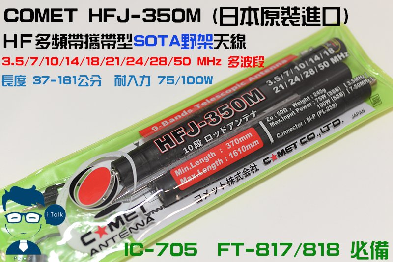
Comet Comet Co., Ltd. is exhibiting a 1.8 to 1.9MHz band extension coil for 3.5 to 50MHz whip antenna “HFJ-350M” prototype with carry case

■3-50MHz 9 band rod element & tap antenna

  • Jacket lead-style frequency tap change
    ●3.5MHz coil attachment
    ●Ten steps of rods for this type of antenna
    ●Approximately 245 g of light weight

Specifications
■Transmission frequency
3.5, 7, 10, 14, 18, 21, 24, 28-29.7 & 50MHz 9 band
■Impedance 50 Ω
■Input-resistant
7-50MHz 100W (SSB)
3.5MHz 75W (SSB)
■Connector M-P
■Full length (mm)- Approximately 370-1610
■Weight (g) – Approximately 245 g (at the time of 3.5MHz expansion coil connection)
■Single model 1/4λ with counterpoise

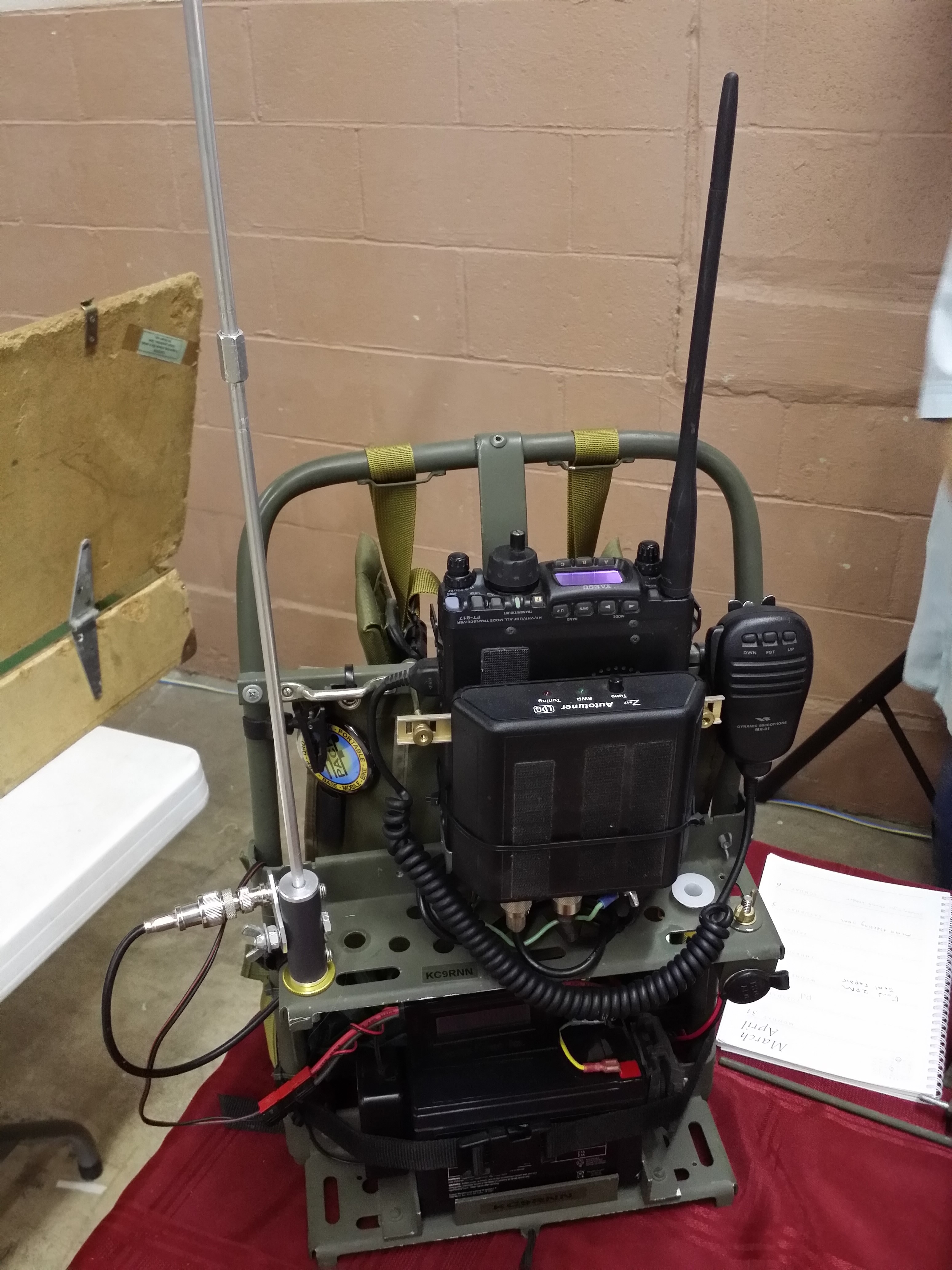
Prototype antenna mount. I have something similar for my Molle pack but SuperAntenna makes a suitable plate as well

Will fit in the backpack or even a vest pocket and a japanese version of the walkabout Antenna we have for our FT-817

Prototype carry case for the Comet  tapped antenna

Diamond Screwdriver antenna mounted on the side using the custom plate

One hand radio

This HFJ-350M antenna seems very interesting

The Diamond HFV40 has been around for some time

A close up of the HFJ antenna

A plastic plate to hold the radio in using the tripod mount on the bottom

Ground lug looks very useful

Get the tripod out for mounting the radio in the car , on a shelf or in the backpack


90 Days away from purchase!

SOTA Activation W1/AM-381 Mt Agamenticus

This is an easy drive up to the summit type operation and is perfect for the tourist or business traveler.

This makes it a lot simpler to get an activation in the log.

I did let the Ranger know what I was planning to do and they were very pleased with the ask first approach. I used a and was anxious to try out the Xiegu G90 Radio as the built in tuner would make things easier to get going. I didn’t think I would have the room to get set up a proper linked dipole for 40m and 20m. So I focused on 20m contacts

This is also a commercial site so my handheld was getting desensed but I did manage to squeeze out a simplex contact with N1DID who was mobile. I could practically see her from the summit driving down I95.

Pretty much a simple activation with wonderful views and a great interpretation center and gift shop.

The highlight was working NM8GS which was a USA-394 Lighthouse activation from Light Ship Huron in Port Huron Michigan. Also working W0MNA in Kansas made the longest distance that day.

Xiegu G90 Power Draw on Transmit Test

I love the G90 for its fast built in antenna tuner and 20W power output. With the lack of sunspots the availability to have some extra power is handy. Its either a 1 or 2 S unit increase depending on the receiving ends radio

Xiegu claims 8A draw which seemed a bit high compared to other radios so I benched the radio after doing the Power Pole mod to measure what reality is

I found the following @13.8 Volts using a number 12 gauge power cable to my PSU with CW

Power Output       Current Amps

5W                        2.9

10W                     3.5

15W                     4.0

20W                    4.5

I use the Bioenno batteries which has proven to be a great match especially for SSB as I can use a smaller battery and use the SSB swings to peak higher with a smaller battery

The antenna was an end fed tossed over the balcony drooping down with easy contacts into the East Coast

QRP Power Reference Levels

Many times we refer to power levels for QRP work. For the FT817 and Elecraft Series of KX radios the 5 watt level seems the normal power output

We can use the following as a guide line as a doubling of power is 3dB and vice versa for -3dB

If we use  “dB5W” as the reference, so that 5W = 0dB, 2.5W = -3dB, 10W = +3dB, 50W = +10dB , 100W = +13dB etc.

A calibrated S meter is 6db between positions.

Thus to be at 5 watts of power to be received at S5 will need 12 dB of extra power to be received at S7 or about 80 -100 watts.

Many times with efficient antennas like a dipole one can be heard at S7 which is totally acceptable. To be the Five by Nine (59) or S9 level again the need to increase power by a factor greater than 10 is required.

QRP works more so in CW than SSB where the rule of thumb is voice needs more power than CW operation.